42 electric motor diagram with labels
Draw a labelled diagram of an electric motor. Explain its ... Working of Electric Motor Current in the coil ABCD enters from the source battery through conducting brush X and flows back to the battery through brush Y. The current in arm AB of the coil flows from A to B. In arm CD it flows from C to D, that is, opposite to the direction of current through arm AB. How to Read Electric Motor Nameplate Data ~ Learning ... Motor nameplate data can be categorized according to the following parameters: (a) General Data (b) Electrical input (c) Mechanical output (d) Motor Design (e) Performance (f) Safety (g) Reliability (h) Construction Nameplate data is the critical first step in determining motor replacement. It is a treasury of important information about a motor.
Electric Motor Diagram Stock Illustrations - 392 Electric ... Download 392 Electric Motor Diagram Stock Illustrations, Vectors & Clipart for FREE or amazingly low rates! New users enjoy 60% OFF. 184,213,689 stock photos online. ... Types of electric vehicles with labeled battery and motor outline diagram. Educational scheme with hybrid, plug-in and electricity car power supply vector ...
Electric motor diagram with labels
PDF Electrical Symbols and Line Diagrams - University of Florida A line (ladder) diagram is a diagram that shows the logic of an electrical circuit or system using standard symbols. A line diagram is used to show the relationship between circuits and their components but not the actual location of the components. Line diagrams provide a fast, easy understanding of the connections and use of components. inspectapedia.com › electric › Electric_MotorElectric Motor Rotation Direction, Which way does an electric ... Purple to yellow = rotate counter-clockwise For an example of electric motor wiring that includes wiring to select electric motor speed options as well as direction of rotation see [live link on the topic page I cited] Dayton Electric Motor Wiring Diagram [PDF], Dayton Electric Mfg. Co., 5959 W. Howard St., Niles IL 60714 USA, retrieved 2017/07 ... How To Read An Electric Motor Nameplate Usually labeled as HP or kW, this is the measure of the motors ability to deliver the torque required for the load at a rated speed. hp = 0.746 x kW; conversely, kW =1.34 x hp. Time Rating or duty (DUTY). This designation specifies the length of time that the motor can safely carry its nameplate rating.
Electric motor diagram with labels. Electric Motors: How to Read the Nameplate - WorldWide ... By design, electric motors have standard voltages and frequencies at which they operate. On the nameplate, you can see this sample motor is designed to be used on 460 VAC systems. 169.5 amps is the full-load current for this motor. Revolutions Per Minute (RPM) The nameplate includes the based speed given in RPM. Electric Motor Nameplate Details Explained | Electric ... The nameplate shown in Figure 1 indicates the electric motor is rated 1 HP. With a service factor of 1.15, the motor can be overloaded up to 1.15 horsepower. If the motor is operated in the service factor range continuously, it will cause a reduction in motor speed and efficiency, and an increase in the motor's operating temperature. › wiring-diagramEverything You Need to Know About Wiring Diagram - SmartDraw Unlike a pictorial diagram, a wiring diagram uses abstract or simplified shapes and lines to show components. Pictorial diagrams are often photos with labels or highly-detailed drawings of the physical components. Standard Wiring Diagram Symbols. Most symbols used on a wiring diagram look like abstract versions of the real objects they represent. OMTEX CLASSES: Explain the construction and working of the ... Question 2. Explain the construction and working of the following. Draw a neat diagram and label it. Electric motor. Answer: Electric motor - It converts electrical energy into mechanical energy.. Principle- When a current carrying conductor is placed normally in a magnetic field it experiences a force which rotates the conductor thus mechanical energy is generated.
What is an Electric Motor? with the Help of a Labelled ... An electric motor is a device that converts electrical energy into mechanical energy. Diagram: Electric motor Working of an electric motor: An electric motor works on the principle of magnetic effect of electric current. Electric Motor Diagram High Resolution Stock Photography ... In the new. . Electric railway journal . -frametype to the box type by electric welding, using frame-heads of modern motors. This was very successful,except that the cost was excessive, about $75 per motor.Finally the old bearings were rebuilt along modern lines,as described below, and this completely remedied thetrouble. Three Phase Motor Power & Control Wiring Diagrams Three Phase Motor Connection STAR/DELTA Without Timer - Power & Control Diagrams. Three Phase Motor Connection Star/Delta (Y-Δ) Reverse / Forward with - Timer Power & Control Diagram. Starting & Stopping of 3-Phase Motor from more than One Place Power & Control diagrams. Control 3-Phase Motor from more than Two buttons - Power & Control ... › electric-motor › singleSingle phase capacitor sizing - Electrical Engineering Centre Mar 21, 2011 · When install a motor using capacitor for starting or running methods,we must sizing the rated of capacitor suitable with motor to get correct starting torque and avoid winding from overheating and can cause a damage. This is basically a question of motor design.There is no straightforward regular relationship between capacitance and the motor size in […]
What is an Electric Motor? Diagram & Working ... In this topic, you study Electric Motor - Diagram & Working. An electric motor is a machine which converts electrical enegy into mechanical energy and so its function is exactly the reverse of that of a generator. In fact, the same DC machine can be interchangeably used as a generator or motor depending upon whether the electrical energy is ... Electric Car Diagram - CAR ANATOMY | Car Construction Suspension elastic elements. Car Wheel Anatomy. ELECTRIC CAR. Batteries for Electric cars. Hybrid Construction. Battery lifetime. Electric Motors construction. Permanent magnet synchronous motor. Replacing electric car batteries. Electric Motor Diagrams A Split Phase Capacitor Start Electric Motor may be defined as a form of split-phase motor having a capacitor connected in series with the auxiliary winding. The auxiliary circuit is opened by the centrifugal switch when the motor reaches 70 to 80 percent of synchronous speed. Also known as a capacitor-start, induction-run motor. How To Read The Label on Motors; Ultimate Guide To ... Part two of the series. An introduction to motor types, reading labels, and examples of projects I have made from these motors. I focus on reusing motors sal...
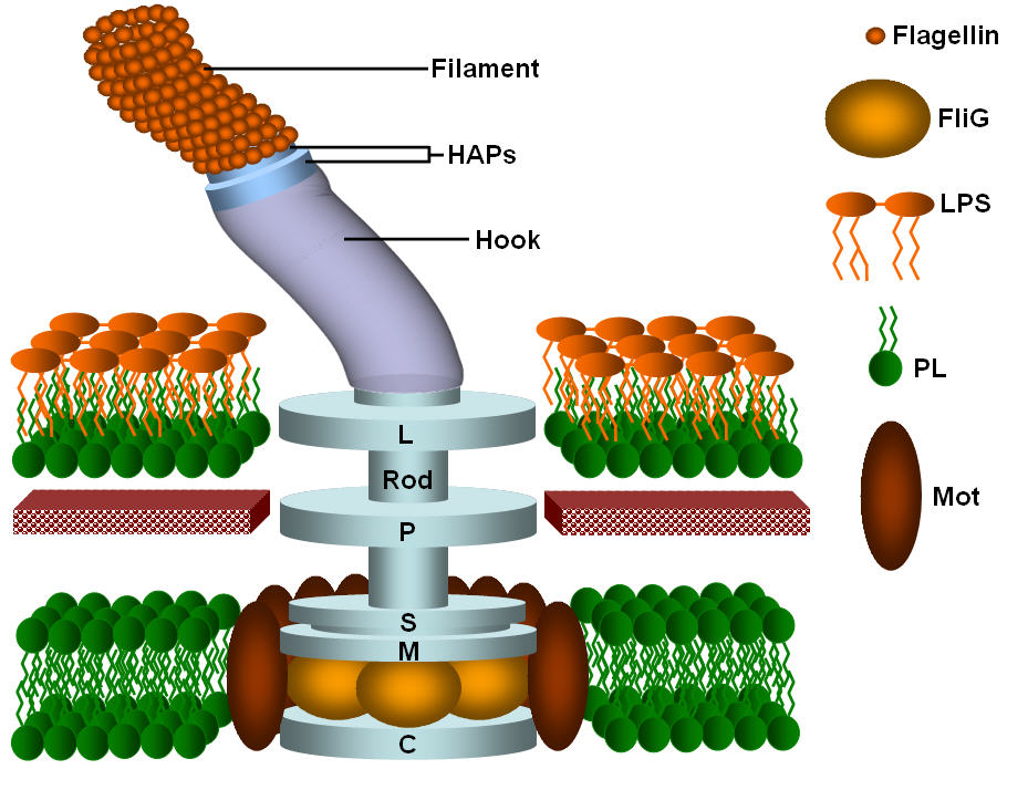
Bacterial flagella - nanotechnology
Electric Motor Diagram Illustrations, Royalty-Free Vector ... Browse 966 electric motor diagram stock illustrations and vector graphics available royalty-free, or start a new search to explore more great stock images and vector art. Newest results Engineering backgrounds. Mechanical engineering drawing Mechanical engineering drawings. Technical Design. Engineering backgrounds. Blueprints. Black background
Electric Motor Diagram High Resolution Stock Photography and Images - Alamy
Electric Motor - Principle, Working, Diagram - Explained ... Electric Motor consists of Rectangular Coil of Wire ABCD A strong horseshoe magnet (or 2 different magnets ) - If we take 2 magnets, North Pole of first magnet faces South Pole of Other Magnet, as shown in figure... The coil is placed perpendicular to the magnet as shown in figure The ends of coil are connected to split rings - P & Q

1999 Ford Taurus System Wiring Diagram cooling Fan Circuit | Schematic Wiring Diagrams Solutions
Question 11 Draw a labelled diagram of an electric motor ... Question 11 Draw a labelled diagram of an electric motor. Explain its principle and working. What is the function of a split ring in an electric motor? Solution Principle: It works on the principle of the magnetic effect of current. A current-carrying coil rotates in a magnetic field.

Perpetual Magnetic Generator: Perpetual Magnetic Motors
Electric Motor Labeled Diagram - need help with bench top ... Electric Motor Labeled Diagram - 14 images - i have a new 2hp 110 220v reversible motor and i m wiring up a reversing drum switch to it, barbara e portfolio abril 2012, magnetism and electromagnetism mcqs with answers electrical academia, electricity work and power,

How Electric Motors are cooled ~ Learning Electrical Engineering
› Electric-Controller-BrushlessElectric Motor Controller, 36V/48V 350W Brainpower Motor ... Suitable for electric bicycles, scooter, etc. Specification: Material: Aluminium alloy Rated Working Voltage: 36/48V Rated Power: 350W Current: 13A Low Voltage Protection: 31/42V Suitable Motor Phrase Angle: 60 / 120 degree Suitable for: electric bicycle, scooter, etc Size: Approx. 9 x 5.3 x 3cm / 3.5 x 2 x 1.18inch Weight: Approx. 204g Package ...

andr01d.make: 2012-07
Draw a labeled diagram of an electric motor. Explain its ... Working of electric motor: As shown in the diagram, when a current is passed through the coil PQRS the coil starts rotating anti clockwise because a downward force acts on length PQ and at the same time an upward force acts on RS. Therefore, the coil rotates in anti clockwise direction.

Engineering Photos,Videos and Articels (Engineering Search Engine): Diagram of a wind turbine
Draw a labelled circuit diagram of a simple electric motor ... With the help of a labelled diagram, describe the working of a simple electric motor. asked Aug 28, 2018 in Physics by AbhinavMehra ( 22.6k points) magnetic effects of electric current

1000+ images about projects on Pinterest | Cars, Boats and Toys
The picture shows a basic diagram of an electric motor ... Armature is the rotating part of the electric motor or generator which contains coils of wire wounded over a metallic core. The commutator plays a crucial role in case of electric motor. The function of the commutator is to reverse the direction of current. The brush is the important part of an electric motor which is connected to the battery.

Types of Earthing Systems Used in Electrical Installations ~ Learning Electrical Engineering
How to Read a Motor Nameplate | VFDs.com Connection diagrams display information about connecting your motor to the proper voltage. Some motors are designed to handle multiple voltages, so there may be more than one diagram. Note: Carefully select the correct diagram. Incorrectly connecting wiring will damage your motor. Model Number and Serial Number

Electrical Engineering World: Basic Parts of a single phase pole-mounted distribution transformers
Motor Connection Diagrams - Electric Motor Warehouse Single Phase Terminal Markings Identified By Color: (NEMA Standards) 1-Blue 5-Black P1-No color assigned. 2-White 6-No color assigned P2-Brown. 3-Orange 7-No color assigned. 4-Yellow 8-Red. Three Phase Connections: Part Winding Start: 6 Leads NEMA Nomenclature: WYE or Delta Connected.
What is an electric motor? Explain its construction and working with the help of a labelled ...
› us › enDelta® Ultra- Light 1000, Semi-Electric Bed - Drive Medical The motor is UL approved ; In the event of a power failure, a 9 volt battery, located in the motor, can lower the head and foot sections nine times ; No crank needed ; New and improved hand pendant has large, easy-to-use controls (Figure E) Bed ships in two cartons ; Channel frame construction provides superior strength and reduced weight

Project: Electric Booger: Motor Basics
PDF Understanding Motor Nameplate Information NEMA v/s IEC ... indicates whether the motor is rated for continuous duty. This is shown as "CONT" on the nameplate. Standard motors are rated for continuous duty (24/7) at their rated load and maximum ambient temperature. Specialized motors can be designed for "short-time" requirements where intermittent duty is all that's needed.

NCERT Solutions, CBSE Sample Papers and Syllabus for Class 9 to 12 : Draw a labelled diagram of ...
PDF Understanding Electric Motor Nameplates In Table 1, there is a column labeled shaft diameter. Figure 2 This is a bottom view of an electric motor showing the mounting bracket and ... VOLTS Electric motors must be matched to the voltage of the circuit. Some motors are only single voltage. If that is the case, then only one voltage will be shown on the nameplate. ...

Patent US4567416 - Device for controlling an electric motor - Google Patents
fueleconomy.gov › feg › atv-evWhere the Energy Goes: Electric Cars - Fuel Economy Electric cars use regenerative braking to recover energy typically wasted in braking. When you apply the brakes, the vehicle's inertia turns an electric motor-generator, producing electricity that is then stored in a battery. The electricity can later be used to power the electric motor, which supplies power to the wheels.

Patent US7073615 - System and method for operating an electric motor by limiting performance ...
› worksheets › ac-motorAC Motor Control Circuits Worksheet - AC Electric Circuits After the motor has had time to speed up, another set of “starter” contacts bypass line power around the resistors, directly to the motor windings. Draw a diagram showing how this could be done for a single-phase electric motor, using two starter contacts: “R” for “run” and “S” for “start”.
Post a Comment for "42 electric motor diagram with labels"